Choosing a Friction Kelly bar is not simply a matter of matching its diameter to a drilling rig. The bar must transmit torque through its telescopic sections while extending to the required depth. Soil conditions, borehole diameter, drilling method, and available rig torque all affect performance. A bar that looks suitable on paper may struggle when dense layers or repeated casing operations increase resistance.
The Federal Highway Administration’s Drilled Shafts: Construction Procedures and Design Methods (FHWA-NHI-10-016, 2010) emphasizes that drilled-shaft construction depends on site conditions, equipment, and construction procedures. It does not prescribe one Kelly-bar design. That distinction matters. Treat the report as a useful framework, then check the bar manufacturer’s rated torque, allowable crowd force, section lengths, and connection details against the rig’s specifications. On site, even practical details count: the depth markings must remain visible, and the sections must telescope without binding. Small details matter.
This guide explains how to compare bar configuration, drilling depth, torque capacity, and compatibility before choosing. It also highlights where friction bars may suit the job—and where an interlocking bar deserves closer review. A single specification rarely tells the whole story. That assumption is easy to make, and sometimes wrong. Confirm critical values with current manufacturer documentation and project-specific engineering advice; published ratings are not a substitute for checking actual ground conditions.
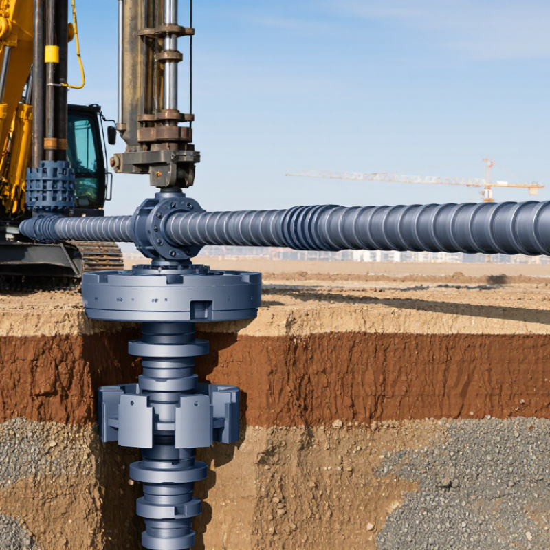
A Friction Kelly bar transfers rotary torque through contact between its overlapping telescopic sections. As the rig turns the bar, friction at those interfaces helps rotate the drilling tool. There are no locking keys to carry torque. Contact condition matters. Wear, debris, or excessive clearance can reduce effective force, especially when the bar is extended under load.
The Federal Highway Administration’s 2010 manual, Drilled Shafts: Construction Procedures and Design Methods (NHI-10-016), describes three construction approaches: dry, casing-supported, and slurry-supported. That distinction matters because ground conditions and drilling method affect the loads a bar may face. Check the rig’s rated torque against the Kelly bar’s capacity, then consider required depth, extension length, and tool weight. A field log helps: record torque, penetration per revolution, and changes between soil layers. Look for steady rotation, not just peak torque. A high reading can signal resistance, but it can also reflect binding. That detail is easy to miss. Soil rarely behaves uniformly, so a tidy calculation may need revision after the first bore.
Understand how torque travels through a telescopic friction bar.
A friction Kelly bar transmits torque through friction at the contact surfaces between its telescopic sections. When choosing one, check that its rated torque and working length suit the rig and the required drilling depth. This diagram shows the torque path only; it is not a measured performance chart.
Before choosing a friction Kelly bar, define the required bore diameter, drilling depth, and ground profile. FHWA’s 2018 Drilled Shafts manual describes shaft applications spanning roughly 0.45 to 3.7 metres in diameter. That range shows why one bar configuration cannot suit every job. Match the bar’s torque capacity and usable stroke to the rig, bucket, and planned depth. Check the geotechnical report for soil layers, groundwater, cobbles, and rock; loose saturated sand may behave very differently from stiff clay. Small details matter. A high water table can affect stability and drilling methods, so confirm seasonal levels rather than relying on a single site visit.
Translate those conditions into a practical drilling plan. In cohesive soil, a friction bar may provide a useful balance of reach and straightforward operation. In dense gravel or weathered rock, confirm that the rig’s available torque and crowd force can handle the cutting tool and formation. FHWA guidance treats groundwater, stratigraphy, and obstructions as key construction considerations; review its 2018 manual alongside current bore logs and site records. Record actual penetration rates and tool changes from nearby projects, if available. Those observations can reveal surprises the investigation missed. I would not size the bar from maximum depth alone; that assumption can be wrong. Check mast clearance, casing needs, and extraction space on the actual pad. A compact site may limit the bar length that works safely, even when the rig’s specifications suggest otherwise.
Before selecting a friction Kelly bar, compare its working limits with the drilling rig’s specifications. Check the rotary drive connection, maximum torque, crowd force, and lifting capacity. The bar may fit the drive but still exceed the rig’s safe operating limits. That mismatch can cause excessive wear or unstable drilling.
Measure the bar’s diameter, overall length, and telescopic stroke against the rig’s mast clearance and available drilling depth. Also verify the Kelly box connection and the drive’s dimensions; small differences can prevent secure engagement. Check the bar’s weight against the rig’s hoist capacity, including the weight of any attached tooling. A quick visual fit is not enough.
Use the rig and bar data sheets, then confirm key dimensions with direct measurements where possible. In practice, records may be incomplete, and a worn connection can be hard to judge. That part deserves a second look. Ask the equipment supplier or a qualified service technician to review uncertain ratings before operation. A careful compatibility check takes time, but overlooking one measurement can turn an apparently suitable bar into a poor match.
A friction Kelly bar should match the rig’s torque, drilling depth, and intended bore diameter. Do not select by length alone. The Federal Highway Administration’s 2018 Drilled Shafts manual discusses shaft diameters of roughly 0.6–3.0 m, a wide range that demands different torque capacity and bar stiffness. Check the rig’s rated torque against the bar’s allowable torque, then compare collapsed and extended lengths with the job depth. Also inspect the overlap between telescoping sections: too little engagement can increase wear and deflection.
Small detail. Big consequence.
Construction material affects weight, fatigue resistance, and service life. High-strength alloy steel can support demanding loads with a thinner wall, while heavier sections may offer more wear allowance but add lifting weight. Ask for the steel grade, heat-treatment details, weld inspection records, and dimensional tolerances—not just “high-strength steel.” World Steel Association data places steel production at about 1.89 billion tonnes in 2023, but that scale says little about the quality of one bar. Request traceable material certificates instead. Compare wear pads and friction surfaces for hardness and replaceability; gritty soil can abrade contact points quickly. I would still leave room for doubt: published ratings rarely capture poor alignment, operator habits, or abrasive ground. Check the bar after trial drilling, especially around welds and section joints.
How to Choose the Right Friction Kelly Bar
Evaluate Quality, Safety, and Long-Term Performance
A friction Kelly bar should match the rig’s torque, drilling depth, and ground conditions. Compare its rated torque with the rig’s working output, not peak output alone. Review the steel grade, section dimensions, weld records, and inspection documents. Ask for straightness and wear limits in writing. A polished finish tells little by itself. Check how the sections extend under load; a poor fit can cause binding and uneven wear.
Safety deserves equal attention. The U.S. Bureau of Labor Statistics recorded 1,075 fatal work injuries in construction in its 2023 Census of Fatal Occupational Injuries. This figure is not specific to Kelly bars, but it highlights the importance of safe equipment handling. Check retainers, lifting points, and contact faces for cracks or deformation before each shift. Keep hands clear during assembly. Small defects matter.
Tips: Request traceable material certificates and a written inspection schedule. Compare expected service life with repair costs, not purchase price alone. Record wear by section, especially after drilling abrasive ground. Fixed maintenance intervals are convenient, but not always sensible; adjust checks to actual wear and duty cycle. Keep the records.


