Emt Electrical Connectors are used to join electrical metallic tubing with boxes, enclosures, fittings, and other raceway sections. Their main purpose is simple: create a secure pathway for conductors while protecting cables from impact, moisture, and movement. A connector also helps maintain continuity between the tubing and the electrical enclosure. That detail matters.
A practical installation may include a set-screw connector, compression connector, locknut, and bushing. Each part has a specific role. The connector grips the EMT. The locknut secures the fitting inside the box. The bushing protects insulation from sharp metal edges. In a crowded junction box, even a small misalignment can stress the conductor insulation. The problem may not appear immediately.
Mike Holt, a veteran electrical educator, expresses the workmanship principle this way: “Electrical safety depends on sound workmanship, not appearance.” His point is useful here. A polished raceway can still hide a loose set screw or an improperly tightened locknut. Installers should check fitting compatibility, tubing size, grounding continuity, and listed requirements. Product markings, manufacturer instructions, and applicable electrical codes should guide the final choice.
This article explains what EMT Electrical Connectors do, where they are installed, and why connector selection affects system reliability. It also considers common mistakes, including over-tightening, poor alignment, and using fittings outside their intended environment. Some installations look correct but deserve another inspection. That uncomfortable step often prevents larger failures.
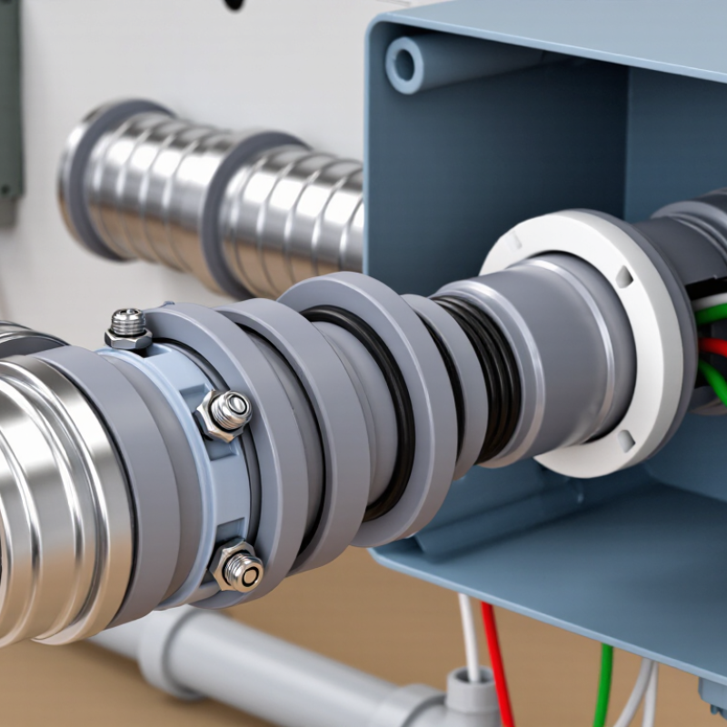
An EMT electrical connector is a listed fitting used with Electrical Metallic Tubing. It joins the tubing to an electrical box, panel, enclosure, or threaded hub. The connector holds the tube firmly and protects conductors at the entry point.
It is not a wire connector.
Most EMT connectors use set screws or compression mechanisms. A set-screw type tightens against the tube with a visible screw head. A compression type uses a nut and ring to secure the tube. Both designs must match the tubing size and installation environment.
Under NEC Article 358, EMT fittings must maintain mechanical protection and electrical continuity. Proper tightening matters. A loose fitting may look acceptable but fail during vibration or inspection.
EMT also commonly supports equipment grounding continuity. NEC 250.118 recognizes metallic tubing as an equipment grounding conductor when installed correctly. NFPA’s Electrical Fires report, based on U.S. data from 2012–2016, recorded about 45,000 home structure fires annually involving electrical failure or malfunction.
Connectors do not prevent every electrical fire, but they reduce exposed edges, movement, and poor bonding risks.
On a real installation, the tube should enter the connector squarely, without sharp burrs. That small detail is often underestimated.
The honest weakness is that visual inspection alone cannot confirm proper torque or bonding. A qualified electrician should verify both.
EMT electrical connectors create a secure transition between electrical metallic tubing and boxes, panels, or enclosures. Couplings, however, join two EMT conduit sections together. Understanding this difference prevents fitting mistakes during installation.
A typical EMT connection begins with a clean, square conduit cut. Remove sharp edges with a reamer. Small details matter. The conduit slides into a coupling or connector until it reaches the proper depth. Set-screw fittings use tightened screws to hold the tubing. Compression fittings use a nut and ring to create mechanical pressure. Both methods depend on correct sizing and proper tightening.
For a reliable connection, keep the conduit straight and free from paint, oil, or metal chips. Misalignment can place stress on the fitting. It may also make wire pulling harder later. At a box, the connector passes through the knockout and is secured with a locknut. This creates a firm mechanical connection and supports electrical bonding. The fitting must maintain continuity across the metal raceway.
In field work, rushed tightening is a common weakness. Too little force may allow movement. Too much force can damage threads or deform thin tubing. Follow the applicable electrical code and the fitting manufacturer’s instructions. Inspect every joint before pulling conductors. A connection that looks acceptable is not always electrically dependable. Test continuity when required, especially on larger or complex installations.
| Data Dimension | Verified Practical Information | Why It Matters |
|---|---|---|
| Primary purpose | An EMT connector joins electrical metallic tubing to an electrical box, enclosure, or other threaded fitting. | It creates a secure mechanical attachment and helps maintain a continuous raceway system. |
| Connection between conduit sections | Two separate EMT sections are joined with an EMT coupling rather than an EMT connector. | Using the correct fitting prevents confusion between a conduit-to-box connection and a conduit-to-conduit connection. |
| Common connector types | Set-screw connectors are commonly used in dry locations. Compression connectors are used where a tighter, more secure connection is required and where permitted by the installation conditions. | The connector style must match the location, enclosure, conduit, and applicable electrical requirements. |
| Typical EMT trade sizes | Common trade sizes include 1/2 in, 3/4 in, 1 in, 1-1/4 in, 1-1/2 in, 2 in, 2-1/2 in, 3 in, 3-1/2 in, and 4 in. | The connector must have the same nominal trade size as the EMT and the correct entry size for the box or enclosure. |
| Connector-to-box attachment | A connector typically passes through a knockout and is secured with a locknut on the inside of the box. A bushing may be fitted on the conduit end to protect conductors. | This arrangement holds the conduit firmly and helps protect wire insulation at the entry point. |
| Set-screw installation | The EMT is inserted fully into the connector, and the set screw is tightened with the appropriate screwdriver or driver bit. | Proper insertion and tightening are necessary for mechanical security and electrical continuity. |
| Compression installation | The EMT is inserted into the connector, and the compression nut is tightened to clamp the conduit. | Compression fittings can provide a secure connection without set screws when the fitting is suitable for the location. |
| Grounding and bonding function | EMT and its fittings can form part of the equipment grounding and bonding path when installed correctly and when permitted by the governing code. | Loose, painted, damaged, or incompatible connections may interrupt electrical continuity and create a safety hazard. |
| Conduit preparation | After cutting EMT, remove sharp edges and burrs with a reamer or deburring tool before inserting the conduit into the connector. | Deburring reduces the risk of conductor insulation damage during installation and pulling. |
| Tools commonly required | A conduit cutter or hacksaw, reamer, tape measure, level, screwdriver or nut driver, and approved torque tool when specified by the fitting instructions. | Using suitable tools helps achieve clean conduit ends, accurate alignment, and reliable tightening. |
| Location suitability | Dry-location connectors are not automatically suitable for wet, damp, corrosive, or hazardous locations. A fitting listed for the specific environment is required where applicable. | Environmental exposure can affect sealing, corrosion resistance, grounding continuity, and long-term reliability. |
| Compatibility check | Verify the connector is listed for EMT, matches the conduit trade size, fits the box knockout, and is approved for the installation environment. | A correct size alone does not guarantee that a connector is suitable for every application. |
| Applicable requirements | Installation should follow the locally adopted electrical code, the fitting instructions, and the requirements of the authority having jurisdiction. | Code adoption and inspection requirements can vary by jurisdiction and application. |
Note: Always de-energize the circuit before working on electrical raceways and confirm installation requirements with the applicable local electrical code.
An EMT electrical connector joins electrical metallic tubing to a box, enclosure, or another fitting. Its job is more than mechanical support. A properly tightened connector helps maintain a continuous metal pathway around insulated conductors. If a live wire touches the tubing, fault current can travel through this pathway toward the grounding electrode system. The overcurrent device should then disconnect the circuit quickly.
The National Fire Protection Association reported an estimated 32,620 U.S. home fires involving electrical distribution and lighting equipment from 2016 to 2020. These fires caused about 470 civilian deaths, 1,100 injuries, and $1.3 billion in property damage. EMT connectors cannot prevent every failure. They can reduce risk when installed with correctly sized tubing, locknuts, bushings, and grounding conductors.
A practical installation check is simple. The connector should sit squarely against the box wall. The locknut must be tight, but not damaged by excessive force. Paint, rust, or loose threads can interrupt bonding. In some installations, a separate bonding jumper is still necessary. Local electrical rules decide that point. This is where mistakes happen. A connector may look secure while offering poor electrical continuity. Testing with an approved continuity meter is wiser than trusting appearance alone. NFPA 70 requires effective grounding and bonding paths, but field conditions still demand careful judgment.
EMT electrical connectors join electrical metallic tubing to boxes, enclosures, and other raceway sections. They create a firm mechanical connection and help protect conductors from impact, dust, and abrasion. In practical installations, the connector also supports a continuous grounding path when the system is assembled correctly.
These connectors are commonly used in commercial buildings, workshops, schools, and light industrial spaces. Electricians install them where conduit enters a metal junction box or panel. They also appear above suspended ceilings, along concrete walls, and beside machinery that needs protected wiring. A connector near a panel may be exposed to vibration, so proper tightening matters. A loose fitting can shift when wires are pulled through the conduit.
EMT connectors are useful in indoor lighting circuits, receptacle runs, control wiring, and equipment connections. Compression and set-screw types suit different installation conditions. The choice depends on the enclosure, environment, and applicable electrical code. In damp or corrosive areas, a standard connector may not provide enough protection. That detail is easy to miss. During inspection, workers should check alignment, thread engagement, connector tightness, and the absence of sharp edges. Not every installation is perfect. A connector can look secure while still failing to bond properly, especially when paint, dirt, or poor preparation interrupts metal contact. Qualified electricians should verify the complete raceway system before energizing it.
EMT connectors join electrical metallic tubing to boxes, enclosures, or other raceways. Choosing the right type protects both the wiring and the grounding path. NFPA 70, Article 358.42, requires connectors to be listed for EMT use. A set-screw connector suits dry indoor spaces, while a compression connector is usually better where vibration or moisture may occur.
Check the connector’s trade size, material, and installation environment before buying. A ¾-inch connector will not properly fit ½-inch EMT. That sounds obvious, but rushed installations create expensive corrections. For grounding, NFPA 70 Article 358.60 recognizes EMT as an equipment grounding conductor when installed correctly. The U.S. Bureau of Labor Statistics reported 126 fatal occupational injuries involving electricity in 2023, so small installation details deserve serious attention.
Cut the EMT squarely, then ream the inside and outside edges. Remove every sharp burr. Insert the tubing fully into the connector and tighten the locknut or fitting according to the manufacturer’s torque instructions. Do not guess. Over-tightening can damage threads, while loose fittings can weaken mechanical continuity. In damp locations, confirm that the connector is approved for that environment and install the required sealing components. I still recommend checking the finished run by hand; even a neat-looking connection may need adjustment.
EMT connectors secure electrical metallic tubing to an enclosure, junction box, or other fitting. Choose a connector that matches the EMT trade size and the installation environment. The chart shows standard EMT outside diameters used when selecting the correct connector size.
Dimensions are standard nominal EMT outside diameters in inches. Set-screw connectors are commonly used in dry locations, while compression connectors may be selected where the connector listing requires protection against moisture. Always verify the connector listing and local electrical code before installation.


