Let’s discuss your container requirements
01708 225350
Call Us
sale@modularmarbles.com
Email Us

What Is a Relief Valve Block and How Does It Work?

A Relief Valve Block is a compact hydraulic assembly designed to control excessive pressure safely. It usually contains a relief valve, drilled passages, ports, and mounting surfaces. Together, these parts direct pressurized fluid through a controlled flow path.

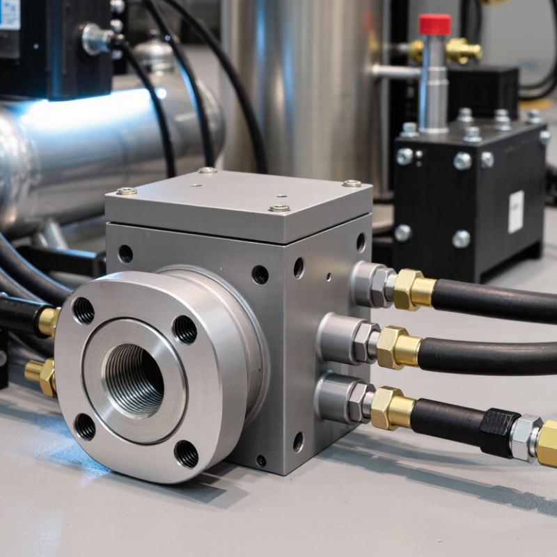
In practical systems, the block often sits between a pump and sensitive components. Picture a steel manifold beside a hydraulic power unit, with hoses connected to clearly marked ports. When pressure rises beyond the valve’s setting, the valve opens. Excess fluid then returns to the tank or another approved circuit path. This action limits pressure and helps protect pumps, cylinders, hoses, and seals from damage.

The operating principle is simple, but accurate selection requires care. Engineers must check flow capacity, pressure ratings, fluid compatibility, connection sizes, and temperature limits. Small errors matter. A valve set too high may fail to protect the system. A setting that is too low can cause weak actuator performance or unnecessary heat.

Maintenance technicians should inspect fittings, mounting bolts, contamination, and leakage during service. Clean hydraulic fluid is essential because particles can prevent the valve from closing correctly. Always compare the block’s markings with the manufacturer’s technical documentation. Field experience shows that installation details often influence performance as much as the valve itself.

This article explains the structure, working sequence, applications, and maintenance considerations of a Relief Valve Block. It also addresses common selection mistakes. Some systems differ considerably, so general guidance cannot replace a verified engineering assessment. That limitation deserves attention.
What Is a Relief Valve Block and How Does It Work?

Definition and Purpose of a Relief Valve Block

What Is a Relief Valve Block and How Does It Work?

A relief valve block is a compact manifold that controls and protects pressurized fluid circuits. Its main purpose is simple: prevent pressure from exceeding a safe design limit. The block may combine a relief valve with isolation valves, test ports, gauges, or drain connections. This arrangement reduces piping, limits leak points, and makes inspection easier in crowded equipment spaces.

Inside the block, a spring-loaded poppet or spool responds to system pressure. When pressure rises above the preset value, the valve opens and redirects fluid toward a tank, return line, or safer low-pressure path. Once pressure falls, the spring pushes the valve closed. The exact response depends on flow rate, temperature, fluid cleanliness, and backpressure. A small setting error can create unstable operation. That detail is often underestimated.

Tips: Confirm the pressure setting against the equipment specification. Check flow capacity, port size, and fluid compatibility before installation. Keep test ports accessible for maintenance. During inspection, look for leakage, damaged seals, blocked passages, and unusual vibration. Never assume a closed isolation valve is harmless; trapped pressure may remain inside the block. A pressure gauge helps, but it does not replace controlled depressurization. Regular testing is wise, although testing intervals should reflect operating conditions rather than a convenient calendar date.

Main Components and Their Functions

A relief valve block is a compact hydraulic assembly that controls excessive pressure. It usually connects a pump, actuator, and return line through drilled internal passages. The block body provides a rigid mounting surface and keeps connections organized. In practical installations, this reduces external tubing and potential leak points.

The relief valve is the main protective component. A spring, poppet, or spool holds the flow path closed during normal pressure. When pressure reaches the adjusted setting, hydraulic force overcomes the spring force. The valve then opens and redirects fluid to the reservoir or a safer circuit. A relief valve block may also include inlet and outlet ports, threaded connections, seals, and a pressure gauge port. An adjustment screw changes spring compression. Small changes matter.

Some blocks contain isolation valves, check valves, or test ports. An isolation valve can separate the assembly during maintenance. A check valve prevents reverse flow. A test port allows technicians to compare actual pressure with the expected setting. I have found that contamination often causes more trouble than obvious mechanical damage. Metal particles can hold a poppet slightly open. Pressure then falls slowly, although the valve may appear correctly adjusted. Sizing is another common weakness. A valve can have the right pressure setting but insufficient flow capacity. That mistake may create heat, noise, and unstable actuator movement. Inspection should include cleanliness, seal condition, torque, and measured system pressure, not only visual appearance. Dials can mislead. Calibration deserves attention.

How a Relief Valve Block Controls Pressure

A relief valve block is a compact assembly that manages excessive pressure in a hydraulic or pneumatic circuit. It usually contains a relief valve, adjustment mechanism, fluid passages, and connection ports. The block keeps these parts aligned and reduces external tubing. That matters in machines exposed to vibration, heat, and limited installation space.

How a Relief Valve Block Controls Pressure

The valve monitors pressure at its inlet. When pressure rises above the preset value, fluid pushes against a spring-loaded poppet or spool. The valve opens and redirects fluid toward a return line, reservoir, or safe discharge point. Pressure then falls. Once it reaches an acceptable level, the spring closes the valve and normal flow continues.

Small details affect real performance. A clogged passage can delay pressure release. An incorrect spring setting can allow damaging pressure peaks. Valve sizing also matters because a small opening may not release enough fluid during a sudden surge. During inspections, technicians should check leaks, damaged seals, adjustment security, and gauge readings. They should also verify the setting with calibrated test equipment, not by appearance alone. Relief valves are not perfectly instantaneous. Temperature, fluid viscosity, wear, and contamination can change their response. That limitation is easy to overlook. A reliable installation therefore needs correct sizing, compatible materials, clear flow direction, and regular testing under controlled conditions.

What Is a Relief Valve Block and How Does It Work? - How a Relief Valve Block Controls Pressure

Data Dimension Description Typical or Verified Information Pressure-Control Relevance
Definition A relief valve block is a compact manifold or valve assembly used to connect, isolate, test, drain, or route flow around a pressure relief valve. It may contain isolation valves, a relief valve connection, a test port, a drain port, and internal passages. It supports safe and controlled pressure protection but does not replace the relief valve itself.
Primary Function To provide a controlled connection between protected equipment, the relief valve, and the discharge or return line. The block can simplify installation and reduce the number of separate fittings and pipe joints. Fewer connections can reduce potential leak points and make pressure-protection equipment easier to inspect.
Pressure-Sensing Point The inlet passage exposes the relief valve to the pressure of the protected system. The sensing pressure should be taken from a suitable point where pressure is representative of the equipment being protected. Accurate sensing helps the relief valve open at its specified set pressure.
Normal Operating Condition The relief valve remains closed while system pressure stays below its set pressure. The block normally allows the protected system to operate without intentional discharge through the relief path. Keeping the relief valve closed prevents unnecessary loss of fluid and maintains normal system operation.
Overpressure Condition When system pressure reaches the valve’s set pressure, the relief valve opens to discharge or redirect excess fluid. Opening pressure, blowdown, reseating pressure, and flow capacity depend on the valve design and service conditions. The relief path limits pressure rise and helps prevent damage caused by excessive pressure.
Pressure-Relief Element The relief valve uses a spring, pilot mechanism, or another calibrated force to keep the valve closed until the set pressure is reached. Common relief valve designs include spring-loaded and pilot-operated types. The calibrated mechanism determines when the valve opens and how it responds to changing pressure.
Isolation Function An isolation valve may allow the relief valve to be separated from the process for maintenance or replacement. Isolation arrangements require careful design because an incorrectly closed valve can disconnect the equipment from overpressure protection. Isolation must not unintentionally disable the only available pressure-relief path during operation.
Testing Function A test port can be used to verify valve response, pressure indication, or the condition of connected passages. Testing may be performed with suitable calibrated equipment and according to the applicable maintenance procedure. Testing confirms that the relief valve and its connection remain capable of responding at the required pressure.
Drain or Vent Port A drain or vent connection can remove trapped liquid, gas, or residual pressure from the block during servicing. The port should discharge to a safe location compatible with the process fluid. Controlled depressurization reduces the risk of unexpected release during inspection or maintenance.
Flow Direction Flow normally enters from the protected system and exits through the relief valve discharge path when the valve opens. Directional arrows, port markings, or installation drawings identify the intended flow route. Correct orientation helps prevent restricted flow, improper valve operation, and installation-related pressure errors.
Materials Block materials are selected according to pressure, temperature, fluid compatibility, corrosion exposure, and mechanical requirements. Common material categories include carbon steel, stainless steel, alloy steel, and other engineered alloys. Material compatibility helps preserve pressure integrity and prevent corrosion-related leakage or failure.
Connections Connections may be threaded, flanged, socket-welded, butt-welded, or otherwise specified for the installation. Connection selection depends on nominal size, pressure class, temperature, fluid type, and applicable engineering standards. Properly rated connections prevent leakage and maintain the required pressure boundary.
Pressure Rating The block and every connected component must be rated for the maximum allowable working pressure and temperature of the service. The lowest-rated component generally limits the allowable operating conditions of the assembly. Correct pressure and temperature ratings help prevent mechanical rupture and loss of containment.
Back Pressure Pressure existing at the relief valve outlet can affect opening behavior and discharge capacity. Back pressure may be built-up by the discharge system or superimposed from another pressure source. The block and discharge arrangement should be designed so back pressure remains within the relief valve’s allowable limits.
Flow Capacity The relief path must pass enough fluid to reduce or limit pressure under the identified overpressure scenario. Capacity depends on valve orifice area, fluid properties, upstream pressure, downstream pressure, and temperature. An undersized or restricted path may fail to provide adequate pressure protection.
Typical Applications Relief valve blocks are used in hydraulic, pneumatic, process, instrumentation, and industrial pressure systems. Applications may include pressure vessels, pump systems, gas lines, hydraulic power units, and test equipment. The block provides a compact interface for protecting equipment from pressure exceeding its design limits.
Maintenance Requirements Maintenance can include leakage checks, connection inspection, cleaning, calibration verification, and relief valve testing. Maintenance intervals should be based on service severity, operating history, regulatory requirements, and the equipment manufacturer’s instructions. Regular inspection helps ensure that the pressure-protection function remains available when required.
Main Safety Rule The protected equipment must not be operated with its only relief path unintentionally blocked or isolated. Isolation devices should be secured, interlocked, monitored, or managed by an approved operating procedure where required. Maintaining an available relief path is essential for preventing uncontrolled overpressure.

Installation and Integration in Hydraulic Systems

A relief valve block is a compact manifold that connects a relief valve to a hydraulic circuit. It directs excess pressure toward the tank or a safe return line. This arrangement reduces loose fittings and makes inspection easier.

Installation starts with the circuit diagram, not the wrench. Confirm the block’s pressure, flow, port size, and fluid compatibility. Mount it close to the pump or protected actuator. Keep the relief path short. Long hoses can create pressure spikes before the valve responds. Check the flow arrow carefully. A reversed connection may look acceptable but behave poorly.

Cleanliness matters. Flush the lines, remove thread debris, and protect every open port during assembly. Tighten fittings to the specified torque; excessive force can distort the block. Connect the return line directly to the reservoir when possible. Avoid sharp bends and unnecessary restrictions. A calibrated gauge should sit near the protected section, where pressure changes can be observed clearly. Set the relief pressure below the weakest component’s rated limit. Adjust it gradually while the system reaches normal temperature. Then test pressure, leakage, noise, and actuator movement under realistic loads.

In practice, the first installation is rarely perfect. Gauge location may hide a pressure drop. The return hose may also be too small. Recheck the circuit after commissioning, especially after several operating cycles. Never treat the relief valve as a routine shutoff device. Its job is protection, and reliable integration depends on careful testing.

Relief Valve Block: Pressure Drop Across Flow Rates

A relief valve block protects hydraulic components by diverting excess flow when system pressure reaches the preset limit. The chart shows representative pressure-drop values across a relief valve block as flow increases. Higher flow generally produces greater pressure loss and heat generation, so correct valve sizing and installation are essential.

Maintenance, Safety, and Common Applications

What Is a Relief Valve Block and How Does It Work?

A relief valve block is a compact manifold used around a pressure relief valve. It may include inlet isolation, outlet isolation, and a bleed connection. The arrangement lets technicians remove or test the valve without dismantling the whole pipe section. It appears on pressure vessels, hydraulic systems, compressors, pumps, and steam equipment.

Correct positioning matters. A closed inlet block can disable protection within seconds. API 576, Inspection of Pressure-Relieving Devices, recommends documented inspection, testing, and control of isolation devices. ASME pressure-vessel guidance also requires relief protection to remain available during operation. HSE’s 2023/24 workplace statistics recorded 138 worker fatalities in Great Britain. That figure is not valve-specific, but it shows why small isolation errors deserve serious attention. A checklist can still miss a sticky stem. That is the uncomfortable part.

Tips: Mark normal valve positions clearly. Use locks, tags, and independent verification before maintenance. Confirm pressure has reached zero, then open the bleed slowly while standing away from the discharge path. Inspect for corrosion, damaged seals, blocked passages, and evidence of leakage. Record test pressure, date, technician, and findings. Never rely on a pressure gauge alone; trapped pressure can remain inside the block. In chemical plants, relief blocks often support inspection schedules. In mobile hydraulic equipment, they help technicians isolate accumulators and actuators. Yet convenience can invite misuse. The block should support maintenance, not become a permanent shortcut around protection.

We are proud to support

Registered Company Name: Upminster Containers Limited. Registered Address: Mardyke Works, St Mary's Lane, Upminster, Essex RM14 3PA. Registered Company Number: 00940382
Developed & Maintained By Space Rocket Digital.
chevron-down